Group assignment(Read more about the group assignment.)
Reading the datasheet
Before reading the datasheet i didn't know about any microcontroller.I had no information about electronical components but after reading the datasheet i know more about components.Where Voltage Common Collector and Ground is of a microcontroller.
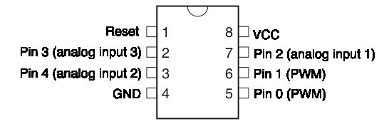
The datasheet also explains which pins are the Pulse With Modulation pins and also the analog pins.
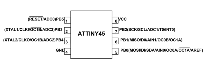
On the ATtiny45 there are also MOSI/MISO and SCK pins
Meaning of the Mosi/Miso and SCK pins are:
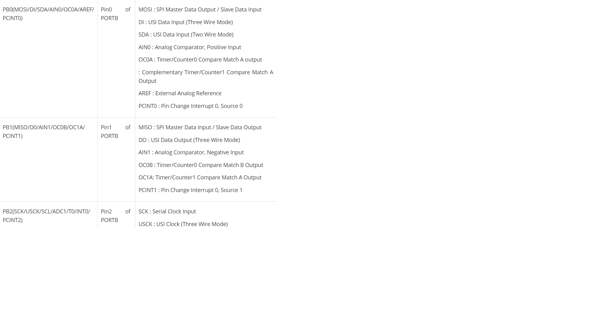
You can also connect the ftdi cable to sent instructions to your microcontroler and this is what i did with the stepper drivers.Giving them instructions by serial.
The questions i have:
1.Do i always need to run the bootloader?
2.Can i use the linkit smart 7688 board as a programmer?
What i want to learn is :
2wsx
1.To program boards that .
2.To read the components names easier and faster because i have a hard time finding components for soldering.
3.I want to learn more about python because now is a little bit hard for me.
Invidual assignment : Program the board to do something
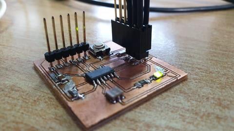
I used the Fab ISP and the Arduino IDE to program my board.
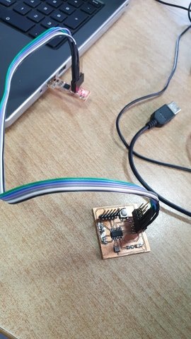
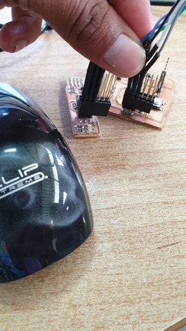
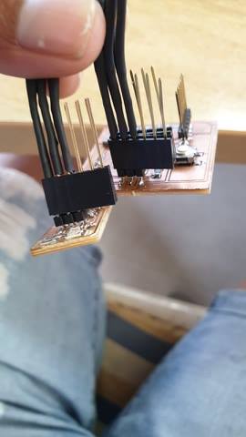
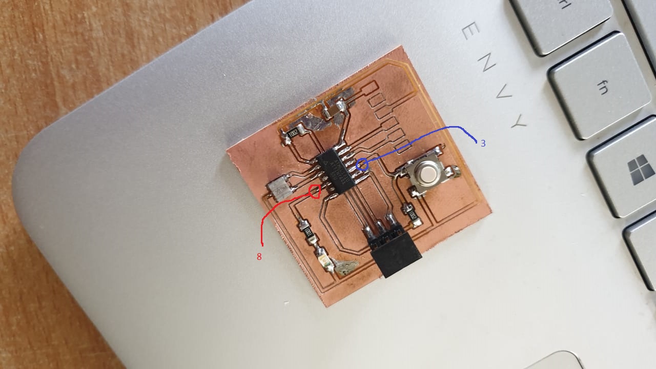
Connect your board on the Fab ISP with the female cables but first you have to know where your VCC and Ground is before you connect them.
Before i began to program ,i downloaded Arduino IDE and usb tiny driver and installed them both my computer to test.
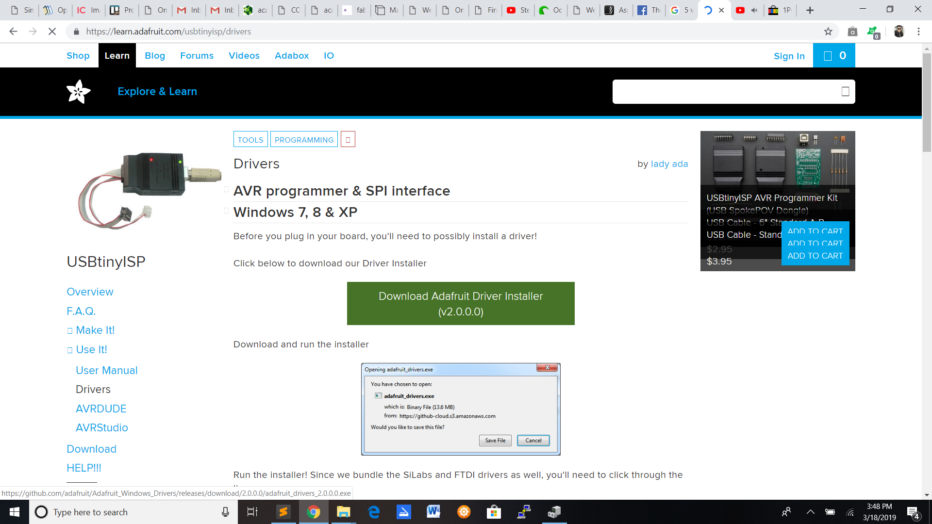
While installing the Arduino IDE ,i also installed https://raw.githubusercontent.com/damellis/attiny/ide-1.6.x-boards-manager/package_damellis_attiny_index.json.Open Arduino IDE and select file and then Click on preferences.Add the link in additional boards manager URLs.
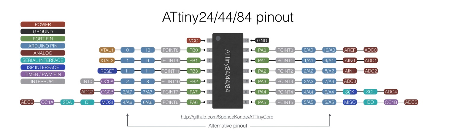
You have to know where the LED and the switch pin is.In my case my LED pin is 8 and my switch pin is 3.
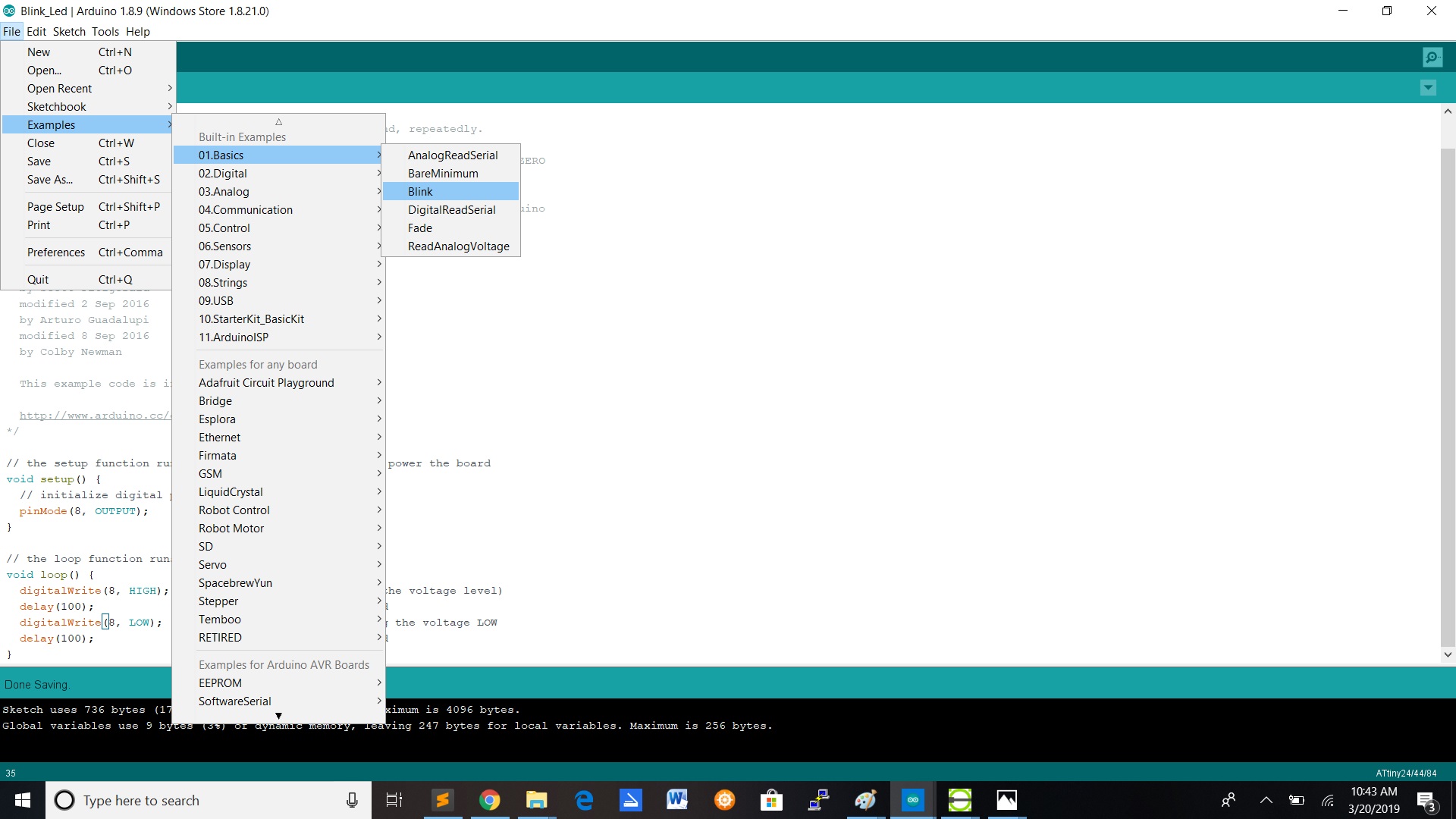
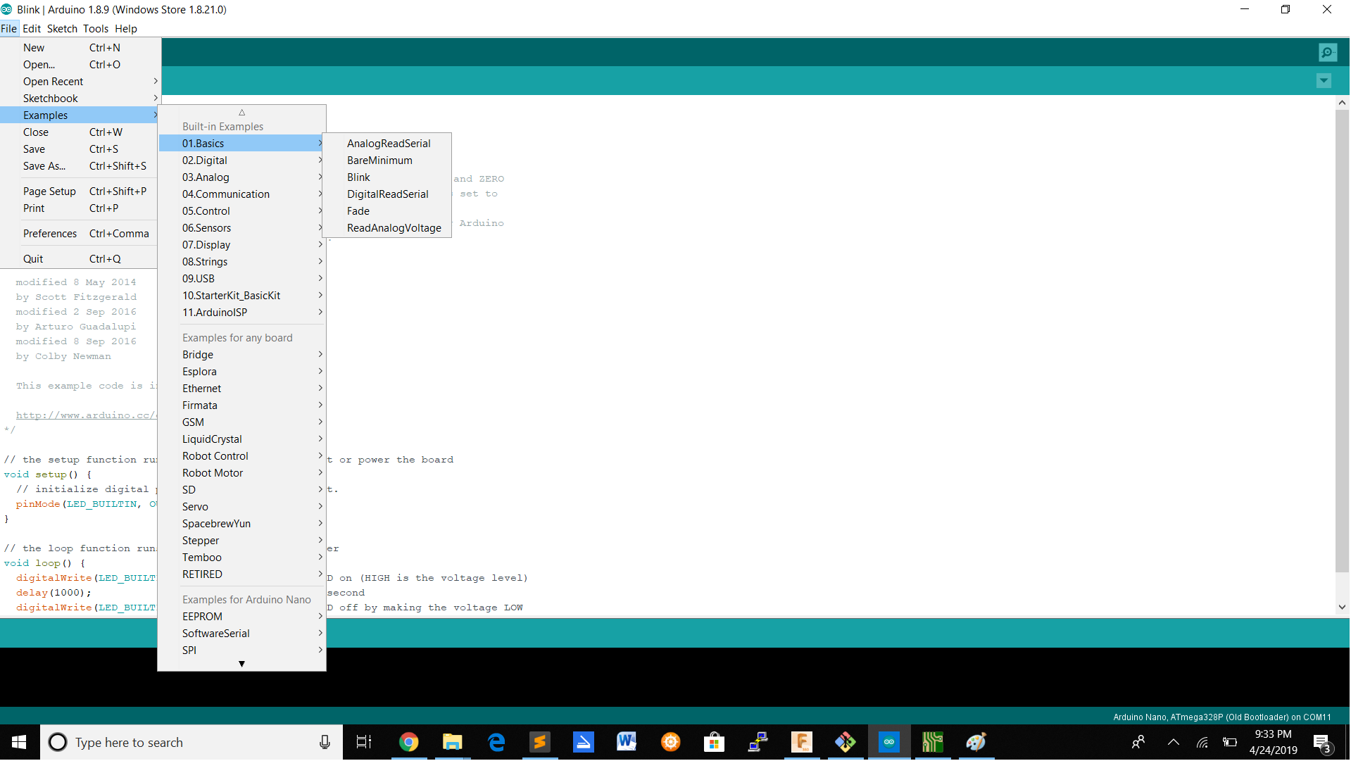
To get the loop,you got to click on file->Examples->Basics->Blink.
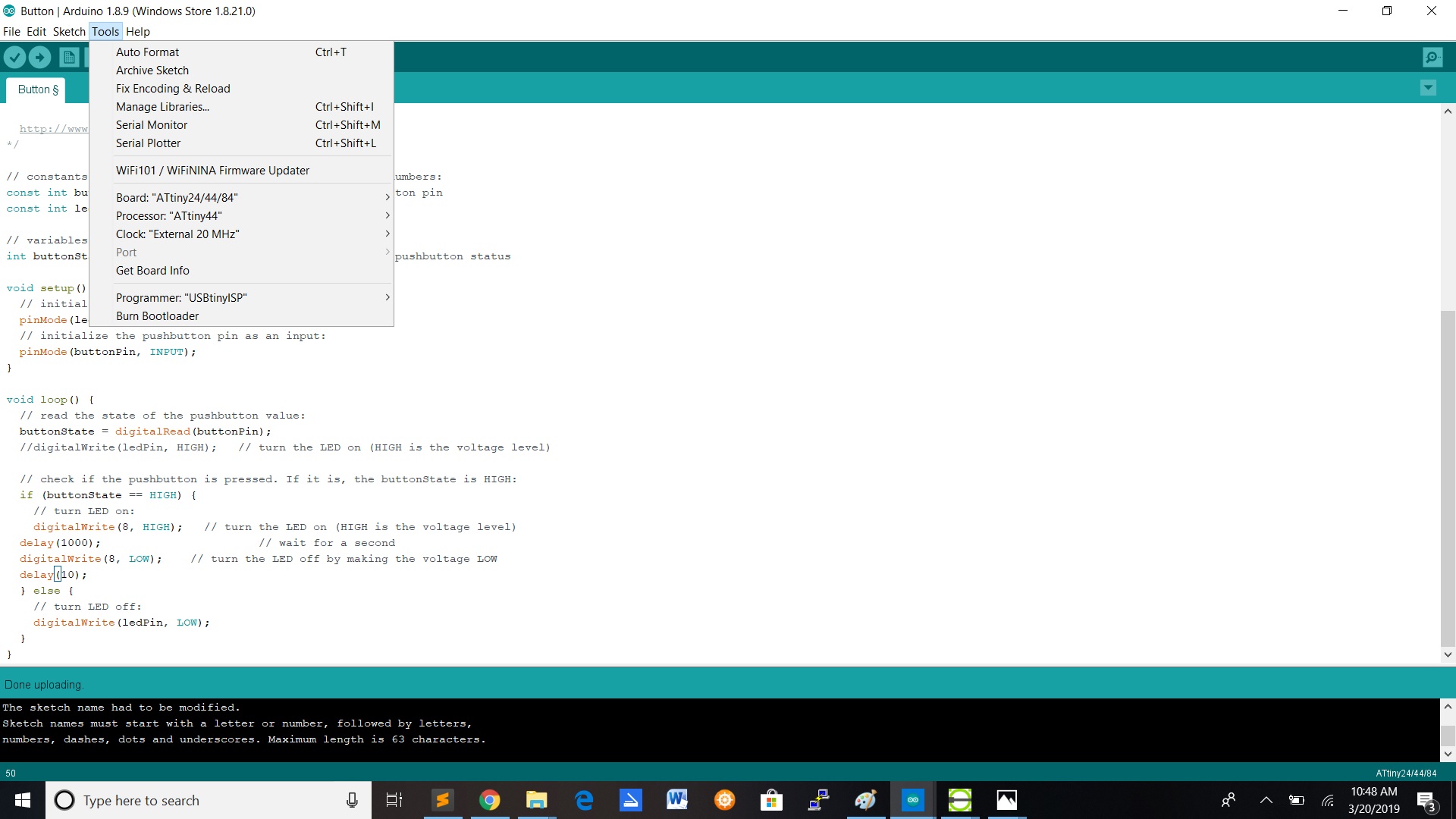
After installing the driver you have to select in Tools,the board (ATtiny24/44/84),Processor(ATtiny44) and Clock(External 20 MHz).
The video shows you a simple LED blink.To get the code you can go to file-> Examples-> Basics-> Blink.
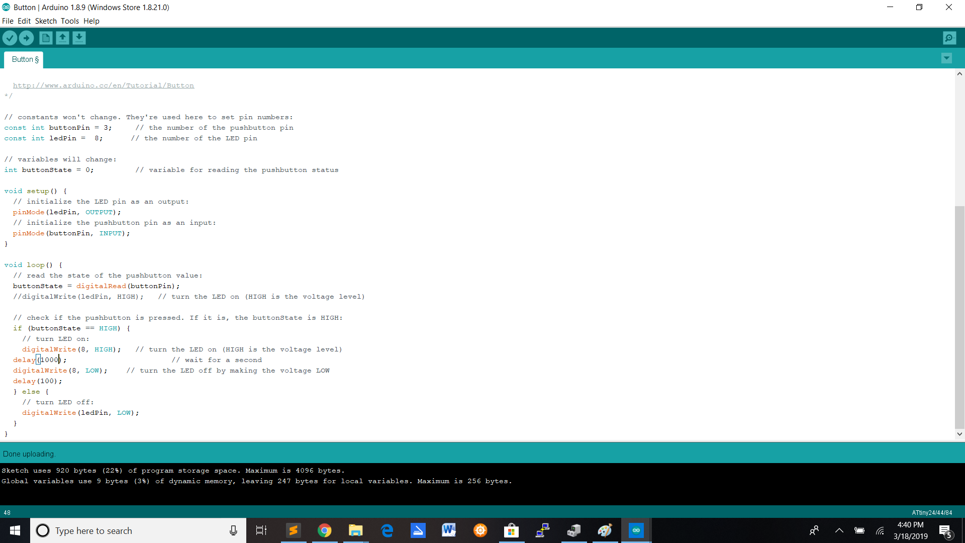
In this video i programmed the led to blink when i push the button.I programmed the Led blink giving it different delays
Programming Process
Programming with the Arduino Nano
1.I took the blink example in the arduino example library.
2.The i search for the VCC and GND pin on my board and then connected the them with female jumper wires and then connected then on the fab isp.I also searched where my LED and Switch pin is.
3.Install the attiny 44 driver.
4.Install the driver in the tools option in the Arduino ide software.
a.Select the board.
b.Select the processor.
c.Select the port.
d.Select the programmer.
5.Run the bootloader
6.Fill in the pin number and run the code
Programming with another languages
Using Neil's code
For the next test i used Neil's code to program my board.
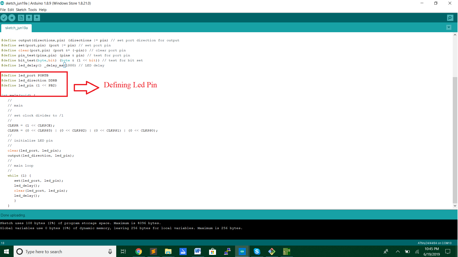
For using this code you need to find the pin which the Led is connected on the Attiny 44.In my case the Led is connected to pin PB2.After uploading the code on the board with the Fab ISP the outcome should be like this :
Using the fading example from arduino IDE
For the other test i used the fading example to test my board.For using the fading example you also gonna define the LED pin.In this case my LED pin is pin 8.
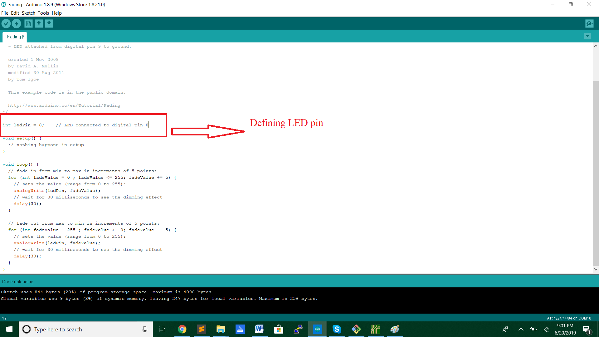
After uploading the code the outcome should be like this:
Files
LED BlinkLED Fading
Neil's code